

27 Feb Reverse Osmosis Technology
Reverse Osmosis Technology
In 1748, a French scientist Abbe Nollett noted that water naturally diffused through a pig bladder membrane into alcohol. It was eventually found that when a semi-permeable membrane separates two solutions of varying concentrations, the dilute solution always flows towards the concentrated solution.
This natural flow of water is called Osmosis. Semi-permeable membranes are very thin layers of material, which allow certain things to pass through them but block others. Cell membranes are, for example, semi-permeable as they allow small molecules like Oxygen, water, Carbon Dioxide, Ammonia, Glucose, amino-acids, etc. to pass through but do not permit larger molecules like Sucrose, Starch, protein, etc.
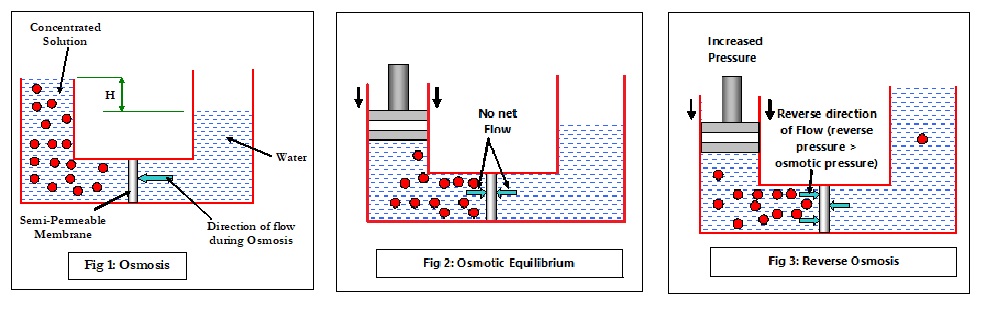
Consider Fig 1 where a concentrated solution is separated from water by a semi-permeable membrane. In the concentrated side, the solute particles constantly collide with each other (Brownian motion), exerting pressure on all sides including the membrane surface. Some water molecules manage to flow through the membrane but are largely restricted by the chaos of the solute particles. On the other side of the membrane, the random movement is far less, allowing more water molecules to flow through the membrane towards the high concentration side, until the hydrostatic pressure (specific gravity x H) will prevent the osmotic flow. Note that the flow of water is on both sides of the membrane, but the NET flow is from lower concentration to higher concentration. Now if a steady reverse pressure (Fig 2) is applied on the side of higher concentration, the net flow (osmotic flow) will start to reduce until the reverse pressure completely stops it. When this happens, there is no net flow of water in any direction and the condition is called as Osmotic Equilibrium. The pressure required to stop or balance the osmotic flow (and thus achieve osmotic equilibrium) is called as osmotic pressure (π) and is calculated as:
π = M . R . T
where, π is the osmotic pressure
M is the moles of solute per liter of the solution, (1 mole = 6.023 x 10²³)
R is the gas constant (0.0821 liter-ATM/Kelvin mole)
T is the temperature in ºK
What happens if the pressure is now further increased? The increased force greater than the osmotic pressure will force a movement of molecules from the higher concentration side to the lower concentration side, as depicted in Fig 3.
In other words, the flow is in the reverse direction of the natural osmotic flow and is, therefore, called Reverse Osmosis (RO). This is the basic concept of reverse osmosis technology. RO is a reversible thermodynamic process, and simply stating, is conceptually designed to produce low TDS (Total Dissolved Solids) water from high TDS feed water by passing the feed water through a semi-permeable membrane. The resultant low TDS water is called Product Water or Permeate, which is virtually free of colloidal, suspended and dissolved matter. The amount of water that can be passed per square foot of the membrane is called Flux and is measured in gallons per square foot per day (GFD).
RO is a cross-flow process
The RO membrane has extremely small pores, < 0.001 micron (1 micron = 1/1000 mm), smaller than even bacteria, virus and dissolved salts. If feed water is directly passed through the membrane, it will plug up the pores in no time. Therefore, RO is used as a cross-flow filtration as opposed to dead-end filtration. In conventional dead-end filtration, the water flow is perpendicular to the filter surface (as shown in fig 4a). In cross-flow filtration (fig 4b), water flows in the same direction as the membrane and prevents dirt and salts from accumulating on the membrane surface.
While part of the raw water is collected as permeate, the rest of the water flows out of the system as Reject water. So, feed water gets divided between ‘Product Water’ and ‘Reject Water’ (drain). If the rejection rate increases, permeate decreases and vice-versa, but together both always sum up to the feed water.
Feed Water = (Permeate) + (Reject)
The reject water is more concentrated than the feed water because of lesser volume of water. The percentage rejection of an RO is calculated as:
Recovery refers to the percentage of feed water obtained as permeate and is obtained by subtracting the rejection percentage from 100.
% Recovery = (100) – (% Rejection)
In commercial Reverse Osmosis Technology Systems, part of the reject water is mixed back with feed water to minimize waste, or directed as feed water to another membrane. In residential POU systems, however, the membrane is usually single pass.
Reverse Osmosis Technology Membranes
The first residential RO membranes were made of cellulose acetate (CA) membrane, which is virtually unused now. Cellulose Triacetate (CTA) membranes have good tolerance towards chlorine and are fairly inexpensive. However, they have limited flux and degrade at higher pH levels. When this happens, the CTA membrane is said to Hydrolyze, a condition characterized by higher throughput but poor TDS rejection. Further, CTA membranes are limited to feed temperatures lower than 85ºF.
Thin Film Composite (TFC) membranes are made of a thin active layer of polyamide polymer coated on a thicker polysulfone layer. In the last 15 years TFC membranes have been the predominant choice for POU RO systems because of their multiple advantages over cellulose membranes. They have higher rejection (better permeate quality), better tolerance to feed water temperatures (100ºF) and high pH values (3 to 11) and more resistant to microbiological attack. Their only downside is their extremely low resistance to chlorine or similar oxidants.
Pre-Treatment
Even with cross flow filtration, RO membranes are susceptible to degradation by several contaminants that eventually result in failure. This degradation is generally referred to as Fouling. The most common foulants are:
a) Hardness
b) Metal oxides
c) Suspended Solids
d) Colloids
e) Microbiological Impurities
f) Oil & Grease
These contaminants must be removed or contained prior to the membrane and together constitute Pre-treatment. Pre-treatment is, therefore, built and designed around the removal of turbidity, metal oxides, hardness, chlorine etc, depending upon the feed water quality. In POU systems, pre-treatment is achieved with a sediment cartridge pre-filter (usually 5 or 1 micron) and a carbon pre-filter to remove chlorine and organics. Simply put, the better the pre-treatment, the better the membrane will perform and the longer it will last.
Factors affecting RO performance
Effect of pressure on reverse osmosis technology
Feed water pressure affects both permeate flux and salt rejection. As shown in figure, permeate flux across the membrane increases in direct relationship to increase in feed water pressure.
However the relationship of feed water pressure and salt rejection is non-linear. As the feed pressure is increased, more salts are rejected initially but with further increase in pressure, some salts are forced through the membrane causing a reduction in rejection. Beyond a point, permeate quality reduces and optimization of quality and quantity becomes important.
Effect of temperature on reverse osmosis technology
Membrane productivity is quite sensitive to feed water temperature. As water temperature increases, it causes a higher diffusion rate across the membrane. Consequently, permeate flux increases almost linearly, but because the salt molecules also start to diffuse to permeate, TDS rejection reduces. RO membranes are usually tested for performance at 25ºC (77ºF).
Effect of Feed Water TDS on reverse osmosis technology
As previously discussed, osmotic pressure is given by:
π = M . R . T
where M is the molar concentration of the water. Clearly, the higher the molar concentration of the solution, the higher is the osmotic pressure.
At constant feed pressure, higher TDS concentration results in lower permeate flux due to the increased inter-molecular collisions near the membrane surface that make it increasingly difficult for water molecules to cross over to the permeate side.
Effect of recovery on reverse osmosis technology
If percentage recovery is increased (and feed water pressure remains constant), it will cause an increased concentration of salts on the surface and depending on their tendency precipitate on the membrane surface as mineral scale. This eventually negates the driving effect of feed pressure, causing permeate flux and salt rejection to decrease and even stop.
For more information on commercial reverse osmosis systems, please click here
For more information on residential reverse osmosis systems, please click here